Qin Youlun, Yuan Qiang, Tu Yu, Research Institute of Ordnance Industry In the field of industrial control and military computers, due to their special power requirements and harsh operating environment requirements, these computers are mostly customized computers. Embedded design solutions based on the CPCI structure and COM Express modules are their preferred solutions, with a short development cycle. , The structure can be customized, easy to upgrade and so on. The X86 architecture embedded computer in the COM Express module is the mainstream CPU architecture, and its on/off management is mainly directed at the ATX power supply design. However, in the field of military control computers, the environmental conditions are very demanding. It is difficult for ordinary ATX power supplies to meet this use-loop requirement, and high-reliability, high-performance power supply modules are often used to provide system power. These power modules are controlled by the enable pins. If you do not determine whether the operating system is safe to exit during shutdown, you can directly turn off the power through the power module enable pins, which will easily lead to system crashes, damage to file information, and even damage to the hardware. . The author designed a non-ATX power supply security switch circuit based on the COM Express module, using the CPLD to detect the system power state provided by the COM Express module, determine whether the operating system is safe to start, whether to safely exit, and provide a security switch function for the system. 1.1 Introduction to COM Express Modules COM Express is a computer module standard defined by PICMG. It is jointly developed by several large embedded industrial computer manufacturers and is an upgraded version of the ETX, XTX, and Qseven standards. In the COM Express specification, some standards including high-speed computer interfaces, including PCI Express, SATA, Gannet, SDVO, etc., have been introduced, and are suitable for use in the case of a standard single-board computer due to limitations in structure or scalability. Because COM Express stipulates a unified user interface to facilitate system hardware upgrades, it is particularly suitable for designing custom industrial and military computers. When designing, the user only needs to focus on the design of the COM Express carrier board and related interfaces according to actual needs. The CPU module is designed by a professional manufacturer, so that the development cycle is short and the reliability is greatly improved. 1.2 Power State Management in COM Express Modules The COM Express specification defines five power states for the operating system: G3, S5, S4, S3, and S0. Three semaphore combinations SUS_S5#, SUS_S4#, and SUS_S3# are used to identify the five power states. The definitions are listed in the table. 1 shows. In the G3 state, the system uses the BIOS battery to power the RTC clock. The external power supply is completely turned off by the mechanical switch. The S0 state is the normal operating state. The S5, S4, and S3 states are managed by the system software. When the system is in the state of S5, S4, and S3, besides the 5V_Standby power supply, the main power supply such as 12V, 5V is not needed. The so-called full security shutdown refers to the system is in the S5 state after running the soft shutdown command. The state of the system can be determined by the states of SUS_S5#, SUS_S4#, and SUS_S3#. Only after the system is detected that the system has been safely shut down can the system be powered off to ensure system security. In the case of ATA power supply, the power can be turned on or off by controlling its PS_ON pin. However, when using a high-performance power supply module, it is generally controlled through its enable pin. The safety switch circuit in this design mainly includes a CPLD control unit, a switch control unit, a clock unit, and a power supply module unit, and its functional block diagram is shown in FIG. 1 . The CPLD control unit mainly completes system state reading, reading of the switch state, power module enable control, timing function; The switch control unit mainly completes the control of the power module enable switch; the clock unit mainly provides the local clock for the CPLD. The power module unit mainly supplies the system with +12V, +5V, +3.3V power supplies. 3.1 Switch Control Unit Design The switch control unit is mainly composed of a double-pole double-throw switch and an NMOS tube. When the power is turned on, the power module enable control is completed. When the power is turned off, a shutdown signal is provided for the CPLD unit. The hardware circuit is shown in FIG. 2. At power-on, the power switch PWR_SW is closed, and the power module unit enable terminal signal PWR_EN is turned on to the ground through the diode and the power switch, and the output voltage is +l2V, +5V, and +3.3V. After the CPLD control unit is powered by +3.3V, it starts to operate. The switch state signal ON_OFF determines that the switch state is closed, and the high-level signal PWR_CRTL causes the NMOS tube (Q1) to conduct to the ground. When turning off the power, the power switch PWR_SW is turned off. At this time, since the NMOS tube is still conducting to the ground, the PWR_EN is valid, the power module unit still supplies power to the external power supply, and then the CPLD control unit detects that the power switch PWR_SW is turned off, and notifies the system to shut down when detected. After the system is completely shut down, the output low signal PWR_CRTL turns off the NMOS, PWR_EN is invalid, and the system power is off. 3.2 CPLD control unit design The CPLD control unit is mainly composed of a CPLD provided by Lattice Corporation, and completes the reading of the status of the main board, the reading of the switch status, the power module enable control and the timing function. Its hardware circuit is shown as in Fig. 3. When the power is turned on, the CPLD control unit detects that the switch status signal is ON_OFF and determines that the switch status is closed, and then outputs a high level signal PWR_CRTL to turn on the NMOS transistor to ground. At the same time, a PWR_BTN# pulse signal is generated to the COM Express module to notify the motherboard to start normally. During shutdown, when the CPLD control unit detects that the switch is off, a PWR_BTN# pulse signal is generated to the main board to notify the system to execute the shutdown command, and then the CPLD control unit determines the status of the main board through the SUS_S5#, SUS_S4#, and SUS_S3# signals. The foot SUS_S5#=0, SUS_S4#=0, and SUS_S3#=0 indicate that the mainboard has safely exited the operating system, the CPLD control unit outputs a low level to turn off the NMOS transistor, and the power module unit enable signal PWR_EN is pulled high (PWR_EN pin internal With a pull-up resistor, the power supply module stops working and the power output is turned off. If the system crashes, turn off the power switch and wait for 2 minutes. The CPLD control unit determines whether the mainboard has not exited the operating system. The CPLD control unit will automatically shut off the power module unit enable end and forcefully shut down the power supply module. Using VerilogHDL language software design, software control process shown in Figure 4. When the device is powered on, it reads the switch status, sends the PWR_BTN# boot pulse to the main board, and sets the PWR_CRTL. When it is turned off, when it is detected that the switch is off, the PWR_BTN# shutdown pulse is sent to the main board, and the local clock provided by the clock unit is used to time. During the time period (2 minutes), the SUS_S5#, SUS_S4#, and SUS_S3# power status indicators provided on the mainboard are used to determine that the system has been safely turned off and PWR_CRTL is cleared to turn off the power module output. If the motherboard has not detected a safe shutdown signal after the timeout period, it indicates that the system has crashed or a problem has occurred in the shutdown process. At this time, PWR_CRTL is forced to clear the output of the power module to achieve the purpose of shutdown. By analyzing the power state management mechanism in COM Express, the author designed a logic circuit based on CPLD, which realized the conversion of the physical switcher into a soft switcher and ensured the safe shutdown of the system. The control circuit has been successfully applied to a certain model project of the author's unit. The actual application results and test results show that the design method is feasible and effective. 144-576V Series Electric Compressor Three-phase Sealed Terminal 144-576V Series Electric Compressor Three-Phase Sealed Terminal,Plastic Connector For Electric Compressor,Ev Air Conditioning Compressor Feedthrough,Ev A/C Compressor Feedthrough Shenzhen Capitol Micro-Electronics Co.,LTD , https://www.capitolgtms.com
Abstract : In order to solve the problem of system breakdown and damage to the system due to non-safety switch on non-ATX power supply of special embedded computer, a non-ATX power switch based on COM Express module was designed. Power supply is turned on or off by controlling the PS ON pin to provide the functional block diagram of the safety switch unit. The design of the switch control unit and the design of the CPLD control unit introduce the design of the hardware, and use VerilogHDL language for software design, and has been successfully applied. In a model project. The results show that the method is effective and feasible, and it can realize the function of converting the physical switch machine into a soft switch machine and ensure the safe shutdown of the system.
Keywords: embedded computer; CPCI; COM Express module; safety switch
0 Preface
1 Technical brief 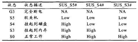
Table 1 COM Express power states
2 overall design 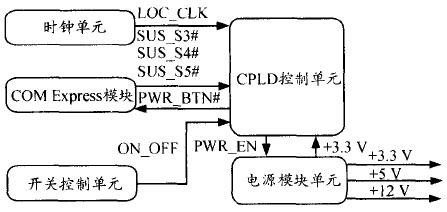
Figure 1 Block diagram of the safety switch unit
3 Hardware Design 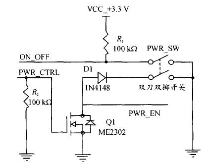
Figure 2 Switch Control Unit Principle 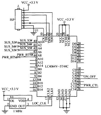
Fig. 3 Principle of CPLD control unit
4 Software Design 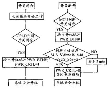
Figure 4 Software Control Process
5 Concluding remarks