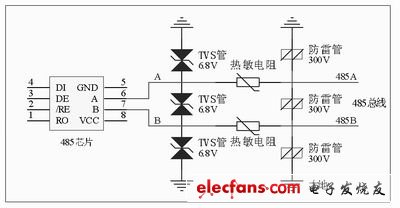
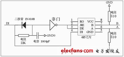
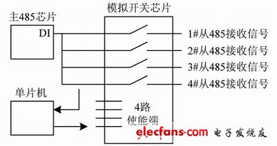
introduction The RS-485 bus is based on balanced transmission and differential reception, has strong anti-common mode interference capability, and is widely used in the field of remote wired digital communications. But it also has some shortcomings, such as a node failure will cause the entire bus to paralyze, can not star wiring. Adding an RS-485 hub on the bus can make up for these defects, while extending the communication distance. This article introduces the design of a four-channel RS-485 hub. This hub has all branches isolated, zero delay automatic transceiver conversion, fault branch automatically cut off and alarm, automatic access after fault recovery and anti-lightning wave Surge protection and other functions. Working principle of RS-485 hub The RS-485 hub uses the master 485 chip to convert the differential signal on the host bus to a TTL level, and then distributes it to the slave 485 chips of other branches by broadcast, and then converts the slave chip into a differential signal and sends it to each branch bus. on. Figure 1 is the application scheme of the four-way hub. The left side of the figure is connected to the upper computer of the RS-485 bus, and the right side is connected to the lower computers of each branch. As can be seen from Figure 1, the RS-485 hub plays the role of the repeater extending the distance and expanding the number of terminals. For a four-way hub, its four branch buses can be wired in a serial manner, which is equivalent to dividing the original set of buses into four groups in a star-shaped manner, which solves the limitations of wiring. In addition, when one of the nodes fails and the bus is short-circuited, it will only affect the branch bus where it is located, but not the other three. Figure 1 RS-485 hub application scheme Figure 2 Schematic diagram of lightning protection surge protection design Figure 3 Schematic diagram of automatic transceiver conversion design Figure 4 Functional block diagram of automatic fault isolation module RS-485 hub design Referring to the working principle of Fig. 1, the design focus of each module is as follows. Power supply design In consideration of isolation protection and anti-interference, the five 485 chips are powered by a 5V isolated power module to isolate the master and slave circuits from each other. Signal isolation design All branch signals are isolated from the main station signal using high-speed optocoupler 6N137 to achieve complete isolation between each branch and between each branch and the main station. Anti-lightning surge protection design As shown in Figure 2, all bus outlets use a detonator and TVS tube to form a two-level protection. When the bus senses a high-voltage and high-energy signal such as a lightning strike, the lightning protection function provided by the lightning protection tube between the line and the ground first allows the lightning overvoltage to be quickly discharged. A peak voltage is induced in the circuit, and the TVS tube used for secondary protection can absorb the peak voltage. If there is a large current, the voltage can be reduced by the high resistance of the thermistor. Zero delay automatic transceiver conversion design As shown in Figure 3, the data input terminal DI of the 485 chip is used to control the transceiver control terminal DE / RE through the NOT gate. The role of resistance and capacitance is to compensate for the delay of signal transmission between DI and DE.
Antenk DIN41612 Connectors are a versatile two piece PCB connector set with feaures useful for many applications including connections for plug-in card and back-panel wiring, PCB to PCB attachment and peripheral connections for external interfaces. Features include a multitude of body sizes and styles with options that include selective contact loading, make and break contacts, contact lead length choices and contact plating variations each in .100" [2.54mm] or .200" [5.08mm] centerline spacing.
The DIN 41612 standard covers a series of two-piece backplane connectors widely used in rack-based telecommunication, computing, process control, medical, industrial automation, test and measurement and military/aerospace systems where long-term reliability is required. They consist of one to three rows of contacts in combinations of 16, 32, 48, 64, or 96 contacts on a 0.1-inch (2.54 mm) grid pitch. The 3 rows are labelled a, b and c and connectors up to 64 way if using a 96 way body can use either rows a+b or a+c. DIN 41612 Signal connectors can be rated to 1.5 amps per signal pin, at 500 volts, although these figures may be de-rated according to safety requirements or environmental conditions. Several hybrid power and coaxial configurations are available that can handle up to 5.6A or even 15A. This wealth of variations explains the very wide range of applications that they`re put to. For over 30 years these DIN 41612 `Euro Card` connectors to IEC 60603-2 have offered a highly reliable system for board interconnects. Precision contact density, low mating forces, a two piece protective design and many contact termination styles offer unlimited design opportunities. Termination methods include – straight PC, solder eyelet, wire wrap, crimp and [press fit" terminals. Insertion and removal force are controlled, and three durability grades are available. Standardisation of the connectors is a prerequisite for open systems, where users expect components from different suppliers to operate together; ept and Conec DIN 41612 are therefore fully intermateable with all other similarly compliant products from other manufacturers like Harting, Erni, Hirose and TE Connectivity, etc.
DIN 41612 Connectors are widely used in rack-based electrical systems. The standard performance of these connectors is a 2 A per pin current carrying capacity and 500 V working voltage. Both figures may be variable due to safety and environmental conditions.
Types
Features and Benefits of Din41612 Connector:
Uses
Applications of Din41612 Connector:
Din41612 Connectors,Din 41612,Eurocard Connector Din41612,Male Din41612 Connector ShenZhen Antenk Electronics Co,Ltd , https://www.antenkconn.com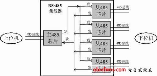
The most common connector in the DIN product line is type C, which is widely used in VMEbus systems, the DIN 41612 standard has been upgraded to meet international standards IEC 60603-2 and EN 60603-2. In the past, ept used a comb supported press-fit tool for their type C and B press-fit female connectors. To be more competitive, ept has changed to flat-rock technology (just a flat piece of steel pushed on the top of the connector) as used by many other manufacturers.
Number of contacts varies
Many variations of housing material, including different types of metal and plastic
Both angled and straight versions
Male and female
C,R,B,Q Type DIN41612 Connectors

Half C, R, B & Q Type DIN41612 Connectors

1/3 C,R, B & Q Type DIN41612 Connectors

H, F, H+F & M type DIN41612 Connectors

IDC Type DIN41612 Connectors

Female Cable Connector

High Pin Count DIN41612 Connectors

Shroud DIN41612 Connectors

• Indirect mating (male/female)
• Automated production processes
• Continuous quality assurance
• 3-160 contacts
• Complete interconnection system
• Numerous interface connectors
• A wide variety of hoods
• Many termination technologies provide for the lowest installed cost
• Contacts selectively gold-plated
• Tinned terminations for increased solderability
The primary use of DIN 41612 connectors are PCB Connectors and motherboards, the main acceptance would be their board to board reliable connections.
Applications
• Data centers
• Storage
• Servers
• Base stations
• Telecommunications equipment
• Backplane and motherboard assemblies
• Switching systems
• Modular rack systems
• Power automation
• Distributed control systems in
industrial control
• Programmable logic controllers (PLC)
• Robotics
• Test and lab equipment
• Energy distribution
• Monitoring equipment
This is not a definitive list of applications for this product. It represents some of the more common uses.