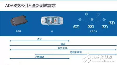
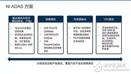
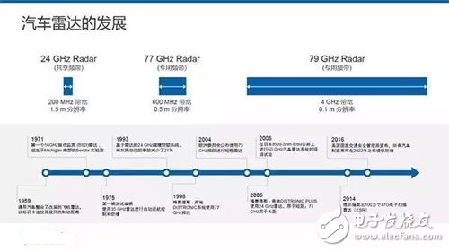
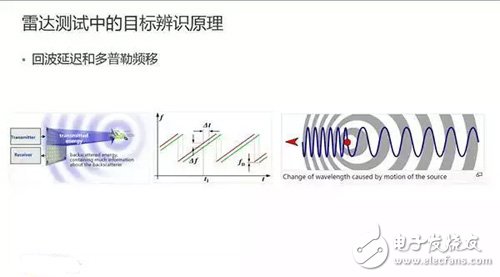
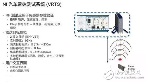
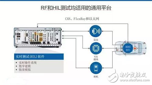
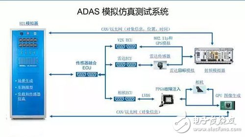
Why are instrument manufacturers, especially RF instrument manufacturers, increasingly entering the topic of autonomous driving? The technological change brought about by this autonomous driving that we see today is very similar to the change that the mobile phone changed from a traditional mobile phone to a smart phone more than a decade ago. Intelligent networked vehicles bring a lot of new technologies to traditionally mechanically-oriented vehicles. The most obvious is that cars are increasingly using sensing and communication technologies. For example, Bluetooth, radar, wireless communication. These technologies actually make the complexity of the entire vehicle-mounted electronic system greatly improved. This increase in complexity is reflected in the growing number of electronic sensors and modules, which is the hardware complexity we are talking about. Secondly, the code of the system algorithms for identification and electronic control will also increase, which is the complexity of the software we are talking about. Regardless of the complexity of the hardware or software, in the quality control process, this is mapped to the topic of "corresponding hardware and software test verification capabilities." Before this sharing, we received an offline question: What are the tests to go through in the process of R&D to production line production of ADAS products? This picture just answers this question. From the type of test, from the laboratory to the production line test, an electronic control module will include several stages of characterization testing, system verification testing, hardware and software in-loop testing, road testing and production line down testing. In today's introduction, we will focus on the functional test schemes of some radar modules, and then introduce some test techniques for scene simulation on this basis. Then we will talk about the fusion test scheme of radar plus camera plus laser sensor and vehicle dynamics model. In addition, we will also mention some test tools for automotive interconnect communication. Functional test solution for radar modules The current automotive radars are available in the 24 GHz and 77 GHz bands. Among the several European and American international radar manufacturers that have the largest shipments, except for Hella, which is still pushing the backward 24GHz products, the other few are basically 77GHz products. This is mainly due to the inherent advantages of 77 GHz technology in terms of module size, angular resolution and high bandwidth resolution. For this reason, 77GHz has been recognized as the mainstream development direction of future automotive radars. Of course, in China due to cost reasons, we can see that there are a large number of 24GHz radars on the market. Including some in the field of non-automobiles. I will briefly review the basic principles of radar target recognition. Like all active radars, automotive radars detect target position and distance information by transmitting beams and then receiving echoes. The current common automotive radar modulation method is frequency modulated continuous wave, also referred to as FMCW. The radar wave is used to discriminate the time difference between the target reflected wave and the self-transmitted wave, and then push the target position by the wave speed. At the same time, by detecting the frequency offset between the reflected wave and the emitted wave, it is judged whether the detected target is close or far away, and how fast it is. This is the principle of Doppler shift. The radar test system provided by NI is also simulated by this principle. The structure of this system is shown in the figure above, including a 3U PXI system host, which contains the control module and the signal unit below 6G. There is a millimeter-wave RF front-end outside the mainframe. Later we will explain why this front-end should be placed outside the host. The front end of the millimeter wave receives the waveform transmitted by the radar transmitter, and then superimposes the delay and frequency shift on the waveform according to the target state (including distance and position information) that the user wants to simulate in the system, and then sends it back to the radar receiver. This makes the radar mistakenly believe that a real moving target object has been detected. A very different point from other radar object simulators in the industry is that our current system includes the transmitter's test function in addition to the target analog function. In other words, the system also integrates another RF analyzer that detects radar antennas and some of the radar power spectrum and time domain characteristics. This is a system that combines testing and simulation. This is a schematic diagram of a more complete laboratory test system setup. The dotted line on the left is the instrument system included in our previous presentation PPT. The blue part in the middle of the picture is a microwave darkroom. The rectangular box on the right is a schematic radar sensor. This radar sensor is mounted on a turntable that can move freely horizontally and vertically. This setting is first of all to meet the radar's measurement function. In general, to verify the radar, first measure some parameters of the radar, including the antenna's antenna direction characteristics. In terms of power, we need to test EIRP. In the spectrum, the bandwidth, waveform width, and noise occupied by the radar transmitter's transmitted signal are detected. In the time domain, the radar signal is also demodulated, and then the modulation time, modulation width, and linearity of the modulated signal are seen. In addition to the additional test functions just mentioned, the device itself is a radar target emulator. In the target simulation, we have to say the difference between single angle and multiple angles. Since any radar simulator transmits and receives radar signals through an RF antenna, in theory, no matter how many targets the device can simulate, these targets can only be limited to the connection between the radar antenna and the antenna of the simulator. on. Simply put, since any radar simulation is a point source, it can only simulate objects that are connected to the connected object and the simulator. This is the single direction we are talking about. In such a one-way simulation process, it is common to simulate AEB, ACC, and of course other scenarios. We can now achieve an instrument distance of 4 to 250 meters and a mobile resolution of 0.1 meters. The above picture shows some common scenarios in a single-target simulation scenario. Includes proximity in any direction, road switching, and target crossing roads. These are all continuous simulations of a single-point simulation scene through software, and can be a single-target scene simulation. Relative to a single goal, we will talk about multiple goals and multiple angles. The angle is actually the core concept here. If an additional baseband module is superimposed on the emulator, and a peripheral RF front end is added, the target simulation of the two directions object can be realized on one instrument. This page explains more vividly what kind of scene requires a radar target simulator with more than two angles. For example, in the case of following the car, it is necessary to identify two cars in different lanes, or to simulate the scene of the third car Cut In or Cut Out while following the car, then we will both be in the two straight directions of the radar. Generate different goals. This explains why we put the analog RF front end of the radar outside the instrument. Since the size of the RF front end itself is relatively small, in this multi-target simulation scenario, the RF front end can be mounted on a movable platform or robotic arm, driving a lateral motion through the device, plus the speed and distance of the instrument itself. Simulation to achieve multi-dimensional object simulation. Testing when machine vision and radar work together This part of the introduction is an introduction to the simulation and testing functions of the radar. When it comes to radar, when it comes to IPG and PreScan, we naturally think about whether machine vision and radar can work together. The answer is of course possible. The combination of machine vision and radar sensors is the current mainstream ADAS collision avoidance method. Our case can connect the machine vision camera to the TASS mainframe, or directly to our host, connect the video and radar simulations together, and synchronize between them to simulate the acquisition of multiple sensors in a real road scene. A road signal. V2X test Another topic of smart connectivity outside the camera is vehicle communication. As the domestic LTE-V standards are still in the process of being developed, our existing car-linking solutions are mainly focused on an agreement such as 802.11p. This includes applications for implementing some car-linked communications, including the so-called basic security messaging in SAE J2735. The common scenario in our car communication is through the agreement, in the process of driving the car, constantly sending their own vehicle safety information to the surrounding vehicles. What we can do now is to provide 802.11p transceiver transceiver modules and some solutions with standard test capabilities. For the transceiver module, it can simulate either a vehicle node or a road test device to perform uplink and downlink vehicle communication data interaction with real vehicles and drive test equipment. This interconnects with other sensors on our car, including radar, cameras, laser sensors and GPS positioning. Sensor fusion test From the radar to the camera, talking about connected cars. That would naturally involve the next topic - sensor fusion. Convergence is also currently a mainstream direction of ADAS technology, the first level of integration is carried out in the ADAS ECU. As we can see from these schemes, it is now possible to technically realize the generation, transmission and synchronization of radar, camera and V2X simulation signals on the same platform. Further fusion, when the car's ADAS ECU receives these signals and passes them to the real car brake control unit. Whether the car can really achieve braking between the expected distances, or the automatic driving change lanes to avoid accidents. This will actually involve the vehicle dynamics model outside the ADAS sensing system, which is the hardware-in-the-loop that adds the vehicle dynamics model. After the integration of the ADAS ECU, we can also load the vehicle's suspension stiffness, tire friction coefficient, vehicle spare weight, road information and weather information into a hardware-in-the-loop vehicle dynamics model simulator. on. The simulator also exchanges data from the ADAS to the vehicle dynamics model through CAN/LIN and previous ADAS ECUs. Ningbo Autrends International Trade Co.,Ltd. , https://www.vapee-cigarettes.com